Technical Knowledge · ISBM Machine
A practical guide for production engineers, packaging managers, and procurement teams — covering the root causes of bottle inconsistency on injection stretch blow moulding machines, how each fault links to a specific mechanical or process variable, and what you can do about it before the problem costs your line another rejected batch.
Applicable to: One-step Injection Stretch Blow Moulding Machines (HGY50-V3-EV, HGY150-V4, HGY150-V4-EV, HGY200-V4, HGY200-V4-B, HGY250-V4, HGYS280-V6, HGY650-V4 and similar platforms)
How the One-Step Process Works
Before diagnosing instability, it helps to have a clear picture of what the machine is doing. The injection stretch blow moulding machine combines three forming operations in one continuous cycle without transferring the preform to a separate reheat furnace. In station one, molten resin — typically PET or PETG in concentrations meeting food-grade or pharmaceutical purity requirements — is injected around a mandrel core at high clamping force. In station two, the preform, while still at its ideal processing temperature, is mechanically stretched along its axis by the mandrel before air pressure between 2.0 and 3.5 MPa expands it radially into the blow mould cavity. In station three, the finished bottle is stripped and transferred to the take-out conveyor. On 4-station machines, an intermediate temperature-conditioning station between injection and blow moulding provides an additional opportunity to equalize preform wall temperature before stretching. All three or four stations operate simultaneously in every cycle, so a fault at any one station affects output from all stations at once.
This tightly coupled architecture is what makes the one-step injection stretch blow molding process so efficient — 40% lower energy consumption compared to two-step reheat-blow systems because no secondary heating is required — but it also means that instability cascades quickly. A 5 °C deviation in barrel zone temperature, a fractional change in air pressure timing, or slight wear in the servo drive system can all manifest as wall thickness variation, uneven neck finish, or dimensional shift across the cavities before the operator notices a trend in the sample data.
Manufacturing Structure: What Each Subsystem Controls
Understanding which part of the machine controls which quality characteristic is the fastest path to diagnosis. The injection stretch blow moulding machine can be divided into five structural subsystems, and bottle instability almost always originates in one of them.
1. Injection Unit (Screw & Barrel)
The injection screw plasticizes raw resin and delivers it at a controlled volume and pressure into the preform mould. Screw diameters across the range start at 40 mm and extend to 60 mm depending on the model, with injection weights from around 188 cm³ to 680 g on large-format machines. The barrel is divided into multiple independent heating zones — 3+N zones on the HGY150 series, 5+N on the HGY50-V3-EV — and each zone must hold its setpoint within a tight band. The screw is heated via a nano-far-infrared energy-saving ring that keeps heat concentrated at the material rather than radiating it into the surrounding structure, which helps with energy efficiency and temperature stability.
2. Injection Clamping System
The injection mould is held closed during preform injection by a high-force clamping unit — 50 kN on the compact HGY50-V3-EV, scaling to 400 kN on the HGY650-V4. This clamping force determines whether the mould parting line holds perfectly tight under injection pressure. Any reduction in effective clamping force — from wear in the tie-bar system, from hydraulic pressure drift, or from mould wear at the parting face — shows up immediately as flash at the neck or body parting line, or as variations in preform wall thickness at the split line positions. Machines using a dual servo motor blow mould clamping system with high-pressure compensation are less susceptible to pressure drift than purely hydraulic designs.
3. Rotary Turret & Angle Divider
The preform is transferred between stations on a servo-driven rotating turret using a high-precision angle divider. This mechanism must position the mandrel core within a fraction of a degree at every station stop — if it doesn’t, the injection mould and the blow mould will not close precisely around the mandrel, leading to off-center preform formation and, downstream, to asymmetric wall distribution in the blown bottle. The turret is driven by a Japan Yaskawa servo motor or a WEICHI servo motor with a Taiwan TSUNTIEN reducer. Any backlash accumulation in the reducer, or loss of encoder count in the servo driver, will cause progressive positioning drift that manifests as cavity-to-cavity variation in bottle wall thickness.
4. Blow Moulding Station
At the blow station, compressed air enters the mandrel and inflates the preform into the cavity shape at pressures between 2.0 and 3.5 MPa. High-pressure valves from Parker (USA) regulate air delivery precisely. The blow mould is closed by either hydraulic cylinders or a dual servo motor clamping system with high-pressure compensation; blowing clamping forces range from 100 kN on the smallest 3-station machines to 400 kN on the HGY650-V4. A gradual drop in blow air pressure — from compressor capacity issues, from a leaking high-pressure valve, or from a worn mandrel seal — allows the preform to under-inflate before the mould cavity is completely filled, producing bottles with low shoulder definition, flat bases, or uneven side walls.
5. Control & Temperature Management System
An integrated control box using Inovance or MiRLE PLC manages servo drives, temperature zones, timing sequences, and clamping pressure across all stations simultaneously. Temperature control directly governs preform viscosity: too hot and the melt is too fluid for consistent injection fill; too cool and the stretch ratio and blow inflation are compromised. 4-station machines add an independent temperature-conditioning station (TEMP. Regulating core stroke of 250–300 mm) that further equalizes preform temperature before the blow station, providing the most consistent wall distribution. Cooling water is circulated at 0.4–0.6 MPa to maintain mould surface temperature; variation in water flow rate or inlet temperature directly alters cycle time and bottle dimensional stability.
Material System: How Raw Material Variables Drive Bottle Instability
The injection stretch blow molding process is particularly sensitive to resin properties because the preform is formed and blown without an intermediate reheat cycle. If the incoming material is inconsistent, the finished bottle will be inconsistent regardless of how well the machine is set up. This is the variable that production engineers in Colombia — and globally — most often underestimate when troubleshooting an instability problem that started after a material batch change.
PET / PETG — Moisture Content
PET and PETG are hygroscopic — they absorb moisture from the atmosphere rapidly after the bag is opened. Moisture levels above 50 ppm in PET cause hydrolytic degradation during plasticization, reducing intrinsic viscosity (IV) and producing a melt that is too fluid to hold consistent wall thickness during injection. The resulting bottle will have variable wall distribution, reduced clarity, and poor impact resistance. Proper pre-drying at 160–170 °C (PET) or 65–80 °C (PETG) for a minimum of 4–6 hours at a dew point of −40 °C or lower is non-negotiable. A moisture analyzer test on every incoming batch should be part of any ISO-compliant quality intake procedure.
Intrinsic Viscosity (IV) Variation
PET IV is a direct measure of molecular chain length. Higher IV (0.80–0.84 dL/g for standard bottles) produces a more viscous melt that holds preform wall shape better during injection but requires higher barrel temperatures and screw back-pressure. Lower IV grades melt more readily but under-fill preform cavities unevenly, particularly in multi-cavity configurations with long hot-runner balancing paths. If your supplier delivers material from different production batches mixed within the same bag, IV variation of as little as 0.02 dL/g between sub-lots can cause cavity-to-cavity weight variation of 3–5% — visible as dimensional differences between identical bottles taken from the same mould in the same shot.
Regrind Contamination & Recycled Content
Adding regrind or post-consumer recycled (PCR) content into a PET feedstock for use on an injection stretch blow moulding machine requires careful IV management. Regrind from a previous production run already has reduced IV from one thermal cycle; using more than 5–10% regrind without IV testing typically worsens preform wall uniformity. For pharmaceutical packaging applications — where Colombian INVIMA registration may specify container extractables and dimensional tolerances — virgin-grade PET or PETG is generally required. Food-grade containers fall under Resolución 683 de 2012, which specifies migration limits that recycled content may not reliably meet without additional testing and documentation.
Colorant & Additive Masterbatch
Colorant masterbatch has its own carrier resin and melt flow index (MFI), which must be compatible with the base PET or PETG. An incompatible or improperly dosed masterbatch creates a melt with non-uniform viscosity across the cross-section of the screw channel, producing streaks, optical cloudiness, or surface defects on the bottle body. UV stabilizer masterbatch can also reduce the thermal stability window, narrowing the injection temperature range within which consistent preform formation is possible. Any masterbatch change should be treated as a process change and validated with a full dimensional measurement run before production restart.
Root Cause Diagnostic Table
Use this table to match the defect you are observing on the production line to the most likely root cause area, then cross-reference with the mechanical or process check list below.
| Defect Observed | Primary Suspect System | Secondary Suspect | First Check Action |
|---|---|---|---|
| Uneven wall thickness, cavity to cavity | Hot runner balance | Servo turret positioning | Weigh preforms cavity by cavity; check hot runner temperature per nozzle |
| Flash at parting line | قوة تثبيت الحقن | Mould wear / parting face damage | Check hydraulic or servo clamping pressure; inspect parting face for wear |
| Cloudy or hazy bottle body | Material moisture / IV | Barrel temperature too low | Moisture test on resin; verify drying time and temperature setpoint |
| Bottle weight varies cycle to cycle | Screw decompression / back-pressure | Injection stroke encoder | Log shot weight for 50 consecutive cycles; check back-pressure setting |
| Flat or under-formed shoulder | Blow air pressure drop | Parker high-pressure valve wear | Monitor blow station air pressure with inline gauge; check valve seat |
| Inconsistent neck / thread dimension | Injection mould temperature | Cooling water flow rate | Verify cooling water pressure (0.4–0.6 MPa); inspect neck insert for wear |
| Bottle warps after stripping | Insufficient cooling time | Uneven blow mould cooling channels | Extend cooling hold time; check mould cooling circuit for blockage |
| Visible gate mark / stress at injection point | Hot runner tip temperature | Injection speed profile | Adjust hot runner tip setpoint; reduce injection speed at gate fill |
| Off-centre base or asymmetric body | Turret angle divider position | Mandrel alignment | Check servo encoder count at station stop; verify mandrel concentricity |
| Bottle too short or too tall | Stretch rod stroke | Preform temperature at blow station | Verify stretch rod stroke parameter vs. mould spec; check TEMP station core stroke |
Critical Process Parameters and Their Stability Bands
Every injection stretch blow molding machine operates within a process window defined by the combination of material, mould geometry, and machine capability. When any parameter drifts outside its stability band, bottle instability follows — often within the next 5 to 10 cycles, sometimes immediately. The parameters listed below are the most critical to monitor during a production shift, and the ones most likely to drift without triggering a machine alarm in older PLC configurations.
| المعلمة | Typical Range (PET/PETG) | Effect of Drift | Monitor Frequency |
|---|---|---|---|
| Barrel Zone Temperature | 240–285 °C (PET); 220–270 °C (PETG) | IV loss, cloudiness, wall variation | Every 30 min |
| ضغط هواء النفخ | 2.0–3.5 MPa | Under-formed shoulders / body | Continuous (inline gauge) |
| ضغط ماء التبريد | 0.4–0.6 MPa | Warping, dimension shift | Every hour |
| درجة حرارة ماء مبرد الزيت | 20–25 °C | Hydraulic pressure instability | Every hour |
| قوة تثبيت الحقن | 50–400 KN (model dependent) | Flash, parting line defects | Each shift start |
| Back-Pressure on Screw | 5–20 bar (application dependent) | Shot weight variation | Each shift start |
| جهد الآلة | 370–400 V | Servo drive faults, timer drift | Each shift start |
| Resin Moisture Content | <50 ppm (PET); <200 ppm (PETG) | Haze, IV degradation, brittleness | Each new lot |
Mould Condition and Its Role in Instability
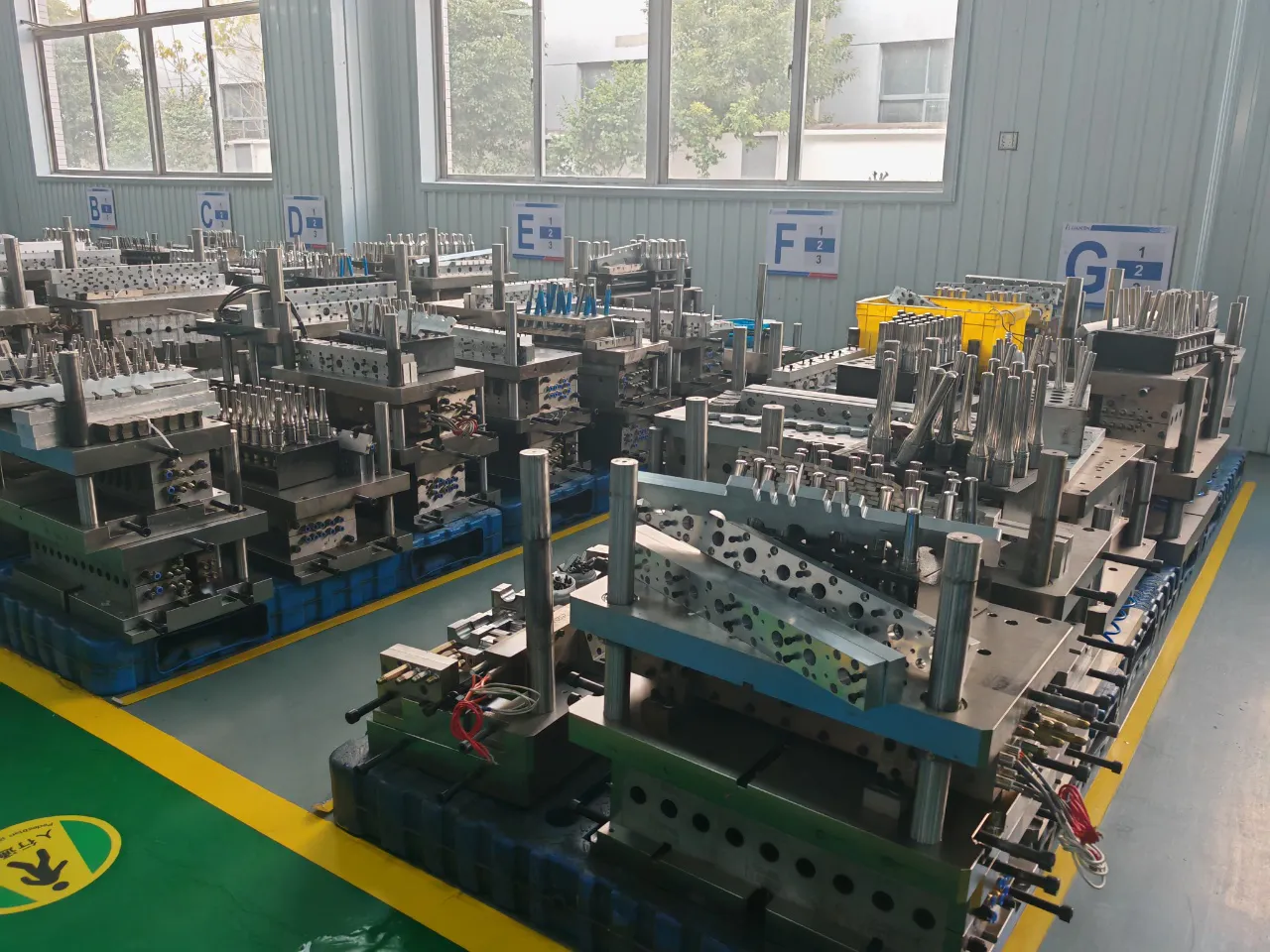
The one-step injection stretch blow moulding machine uses two separate mould sets: the injection mould (preform cavity and neck insert) and the blow mould (final bottle cavity). Both are precision tooling items that wear over time, and both can introduce instability when wear exceeds the tolerance band for the bottle specification you are running. Understanding the One-step Injection Stretch Blowing Mould structure is as important as understanding the machine itself.
The injection mould body is typically machined from stainless steel or high-grade alloy steel to ensure long service life, with the cavity and neck block carrying the most precise dimensions. Over time, the neck insert faces particular wear risk because the mandrel core passes through it at every injection cycle under full clamping force. A neck insert that has worn by as little as 0.05 mm will produce bottles with inconsistent finish dimensions — thread height, neck diameter, or ovality — that cause cap torque failures downstream. The blow mould cavity itself can develop surface wear at the base dome area, where stretch and blow pressure concentrate, or at the shoulder radius where material thickness is thinnest.
For productions where machine compatibility with Japanese ASB or Aoki platform moulds is used (HGY150-V4, HGY200-V4-B, HGY250-V4, and HGY650-V4 models), mould condition management is especially important. An ASB or Aoki mould that has run millions of cycles on its original platform will bring its accumulated wear to the new host machine. Before treating observed instability as a machine fault, the mould history should be reviewed and a dimensional inspection of the neck insert and cavity surfaces should be completed. Replacement injection stretch blow moulding machine mould components are available for these platforms, and sourcing them from an experienced supplier before a quality crisis occurs is always preferable to reactive emergency procurement.
Regulatory Context: Colombia and International Standards That Affect Bottle Quality Requirements
In Colombia, quality requirements for plastic containers produced on injection stretch blow molding machines are governed by several regulatory frameworks depending on the end application. Understanding these requirements matters for troubleshooting because the tolerance bands that define “unstable” output are set — in practice — by what the end-use regulation demands, not just by what looks acceptable on the production floor.
Colombia — INVIMA (Pharmaceutical & Cosmetic)
Pharmaceutical containers must comply with the Colombian Pharmacopoeia and INVIMA registration requirements for primary packaging materials. PET and PETG bottles for oral liquid medicines, eye drops, or pharmaceutical syrups must demonstrate container-content compatibility, dimensional stability, and compliance with extractables limits. Dimensional instability from an injection stretch blow moulding machine that produces bottles outside specified tolerances can result in failed closure torque tests or fill-volume inaccuracies — both grounds for INVIMA regulatory action.
Colombia — Resolución 683 de 2012 (Food Contact)
Food-grade plastic containers produced for the Colombian market must comply with Resolución 683 de 2012 from the Ministry of Social Protection, which sets migration limits for plastics in contact with food. Wall thickness variation from an unstable blow moulding machine process can create zones of locally thinner material that may not provide adequate migration barrier performance — particularly for containers that will hold oils, acetic acid foods, or high-temperature filled products. Producers must document their bottle specifications and material certifications as part of MSPS food contact compliance.
European CE Machinery Directive
One-step injection stretch blow moulding machines exported and operated in EU member states must comply with the EU Machinery Directive 2006/42/EC, requiring CE marking, a Declaration of Conformity, and a Technical Construction File. While this is a machine safety standard rather than a bottle quality standard, it is relevant for Colombian importers who also serve European brand customers with their output: if the machine itself is CE-certified, audits of the production facility by European brand QA teams are less likely to flag equipment non-compliance as a risk factor alongside bottle quality data.
ISO 15747 — Plastics for Pharmaceutical Packaging
Internationally, ISO 15747 specifies requirements for plastic containers for inhalation products, and its principles are referenced more broadly for injectable and oral pharmaceutical packaging. Dimensional consistency from the injection stretch blow moulding machine — particularly neck diameter, ovality, and wall thickness — must be validated against the specification limits in the registration dossier. Bottle instability that was within acceptable limits during the registration sampling may fall outside limits in serial production if process drift is not caught and corrected promptly.
ASTM D2911 — Dimensional Tolerances for Plastics
ASTM D2911 provides the standard specification for dimensional tolerances for rigid plastic containers, widely referenced by North American and international brand buyers when specifying bottle quality requirements. For a Colombian exporter shipping PET containers to the US market, ASTM D2911 compliance may be a contractual requirement even if it is not directly Colombian law. Understanding the tolerance bands in this standard helps production engineers set appropriate internal alert limits in SPC monitoring before a defect reaches the customer.
Step-by-Step Diagnostic Checklist for Bottle Instability
When an injection stretch blow moulding machine starts producing inconsistent bottles, follow this sequence before adjusting any machine parameter. Making process changes without first identifying the root cause is the fastest way to compound the original problem with a second one.
Measure 10 consecutive bottles from each cavity position. Record bottle weight, wall thickness at top / middle / bottom, neck diameter, overall height, and any visual defect location. Identify whether the problem is cavity-specific (one or two positions only) or systematic across all cavities. Cavity-specific problems point to the mould, hot runner nozzle, or cooling channel for that position. Systematic problems across all cavities point to the injection unit, material, or control system.
If production started with a new material bag or batch within the last 2–4 hours, test a sample for moisture content immediately. Confirm the dryer setpoint and dwell time. If you cannot test for moisture, restart with a known-good batch and run 50 bottles before resuming measurement — this will tell you whether the problem is material-driven or machine-driven.
Check compressed air pressure at the machine inlet (target 0.7–1.2 MPa for supply; blow station working pressure 2.0–3.5 MPa). Check cooling water pressure (0.4–0.6 MPa) and oil cooler water temperature (20–25 °C). Check supply voltage (370–400 V). Any of these that are out of specification must be corrected before proceeding — they are the most common silent cause of instability in production environments where the machine is running but the support utilities are drifting.
Access the Inovance or MiRLE PLC alarm log for the last 24 hours. Look for any servo axis position errors, encoder count mismatches, or communication timeouts on the turret drive. A servo axis that is recovering from an intermittent fault without triggering a hard alarm will produce exactly the kind of sporadic instability that is hardest to trace — it looks like a process problem but is actually an electromechanical one.
Install a temporary inline pressure gauge at the blow station air inlet and monitor pressure for 20 consecutive cycles. A pressure that holds constant throughout the blow hold time indicates the valve and delivery system are functioning correctly. A pressure that drops during the hold period indicates a valve seat leak (Parker high-pressure valve), a loose fitting on the air delivery circuit, or a worn mandrel seal. All of these reduce effective blow pressure below the 2.0 MPa minimum needed for complete cavity filling.
If Steps 1–5 have not identified the root cause, open the injection mould and blow mould for inspection. Look for scoring on the parting face, wear at the neck insert bore diameter, carbon deposits at hot runner nozzle tips, or blocked cooling channels. For machines running ASB or Aoki replacement moulds, inspect the taper surfaces on the mandrel and mould core for fretting wear that could be causing positional variation at every cycle.
معلومات عنا
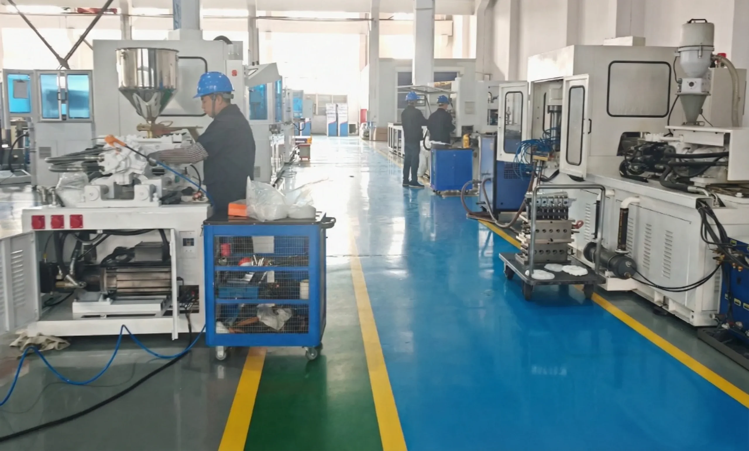
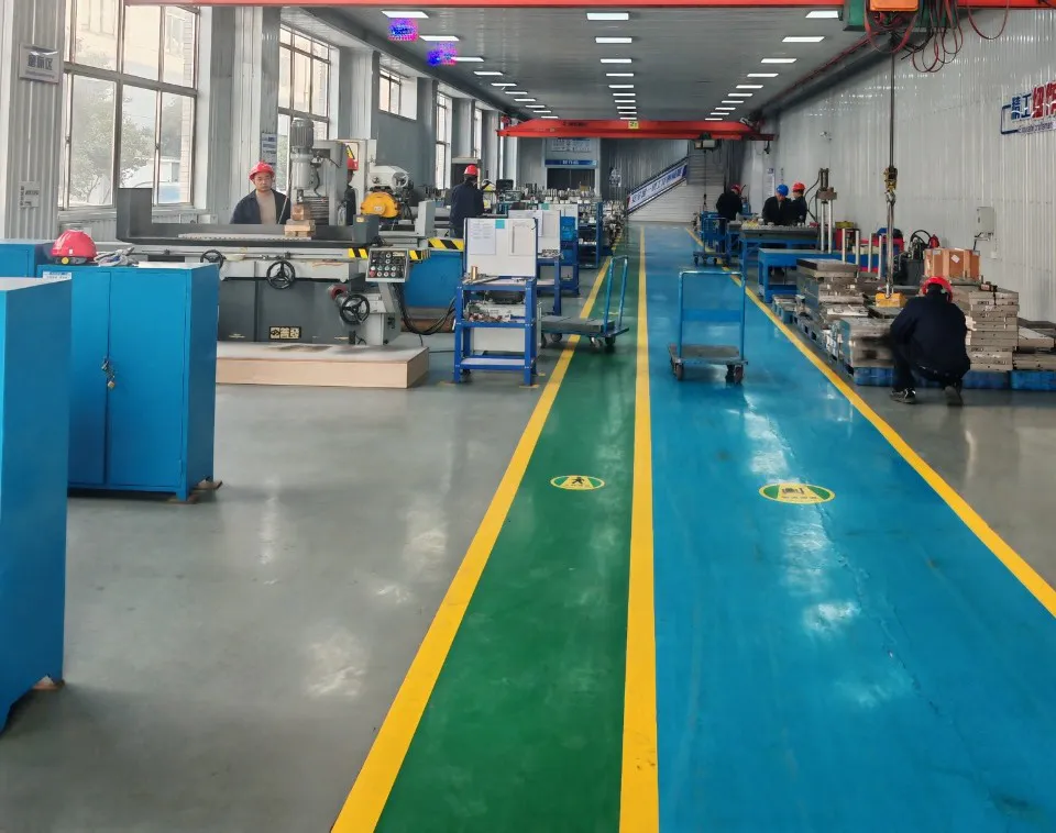
We are a dedicated developer and manufacturer of fully automatic one-step the machines and precision blow moulding tooling. Established in 2003, our operation has grown to occupy a production base of more than 20,000 square meters and has accumulated more than two decades of hands-on experience in the research, production, and after-sales support of blow moulding machinery. Our engineering team has applied for multiple national patents and developed a complete product range of PET/PETG/PC/PCTG/PP blow moulding machines covering cosmetic packaging, beverage containers, pharmaceutical bottles, food-grade containers, baby products, and special-shaped craft bottles. We provide pre-sale engineering consultation, in-production technical support, and a 24/7 service hotline to customers across Colombia and globally, and our machines have entered production facilities serving internationally recognised brand customers across multiple sectors. Our goal is to provide the most cost-effective, energy-efficient, and stable blow moulding solutions available — giving production teams the machine stability and process documentation they need to meet the quality standards their customers demand.
ورشة عمل
الأسئلة الشائعة
Q1. Why does my this equipment produce bottles with different wall thicknesses from one cavity to the next?
A1. Cavity-to-cavity wall variation on an the ISBM almost always traces back to hot runner temperature imbalance or unequal resin filling speed between nozzles. Weigh the preforms from each cavity individually — if they differ by more than 1–2%, inspect each hot runner nozzle tip for partial blockage or temperature deviation. The turret positioning accuracy is the second thing to check: if one mandrel is consistently off-centre, the preform formed on that mandrel will always blow with asymmetric wall distribution.
Q2. What is the best way for a Colombian pharmaceutical packager to validate bottle quality from an ISBM machine before submitting to INVIMA?
A2. For INVIMA validation in Colombia, the recommended approach is to run a process qualification (PQ) batch of at least 3 production runs at full speed, measuring dimensional conformance (neck diameter, height, wall thickness), weight consistency, and visual appearance against the registered specification. Retain sample bottles and material certificates from each run. INVIMA expects documentation that the bottle produced during qualification matches what is described in the primary packaging declaration of the drug registration dossier. Any subsequent process change — including a material batch change or a machine modification — should trigger a re-validation review.
Q3. How do I get a quote for a new injection stretch blow molding machine that can replace an existing ASB platform in my production line?
A3. To receive an accurate quote for an this system as a replacement of ASB and Aoki platforms, provide your current mould model and cavity count, the bottle volume and neck diameter you produce, your required output per hour, and your available floor space. Models like the HGY150-V4-EV and HGY200-V4-B are specifically designed for compatibility with Japanese ASB-12M and Aoki-250 mould formats. Contact our sales team with this information and we will recommend the best model for your specific application and provide a detailed technical proposal.
Q4. Which the blow moulding machine model is most suitable for producing 500 ml pharmaceutical bottles in small-batch runs?
A4. For pharmaceutical 500 ml containers in small-to-medium batch runs, the HGY150-V4-EV is a strong candidate: it handles PET and PETG, supports up to 3 cavities for 500 ml bottles (bottle diameter up to 54 mm, height up to 150 mm), and provides the all-servo control precision needed for the dimensional consistency that pharmaceutical packaging demands. For larger batch requirements, the HGY200-V4 can produce up to 6 cavities of 500 ml containers. Both are compatible with the blowing air pressure range of 2.0–3.5 MPa required for good bottle shoulder definition in pharmaceutical HDPE and PET containers.
Q5. Where can a cosmetic bottle supplier in Bogotá find a reliable injection stretch blow molding machine supplier with proper after-sales support?
A5. When evaluating injection stretch blow molding machine suppliers for a facility in Bogotá or elsewhere in Colombia, look for suppliers who provide documented after-sales protocols: on-site commissioning engineers, a spare parts inventory commitment, a 24/7 technical hotline, and a remote diagnostic capability for PLC fault reading. The quality of after-sales service — not the machine price — is the factor that determines actual cost of ownership over a 5–10 year production life. Ask prospective suppliers for references from cosmetic bottle producers in similar applications and request their average response time for emergency fault resolution.
Q6. What is the injection stretch blow molding process advantage for cosmetic bottles compared to two-step reheat blow moulding?
A6. The one-step injection stretch blow molding process combines injection, preform conditioning, stretching, and blow moulding in a single machine without a separate reheat furnace. This eliminates the secondary heating energy cost (approximately 40% energy saving), removes the risk of preform contamination during storage and transfer, and produces a more consistent preform temperature profile at the blow station — which directly improves wall thickness uniformity and optical clarity. For high-end cosmetic packaging where surface finish, transparency, and dimensional consistency are paramount, the one-step process delivers more consistent injection stretch blow molding products than two-step alternatives at comparable cavity counts.
Q7. How does the servo drive system on a new this production unit improve bottle quality over older hydraulic designs?
A7. All-servo the stretch blow moulding systems (such as the HGY50-V3-EV with 5 servo control systems, or the HGY150-V4-EV with 10 servo drives) offer position repeatability of less than 0.05 mm on each axis, compared to 0.1–0.3 mm typical of conventional hydraulic designs. This precision directly reduces cavity-to-cavity variation and cycle-to-cycle dimensional drift. Servo drives also respond to load changes in real time, maintaining consistent clamp force and stroke speed even as mould temperature changes over a long production run — something hydraulic pressure control valves do only approximately.
Q8. When should a food-grade PET bottle producer in Colombia consider switching from extrusion blow moulding to the units?
A8. The switch from extrusion blow moulding to injection stretch blow moulding makes economic and quality sense when your production requires: consistent neck dimensions for a specific cap torque specification, bottle weight variation of less than 1% (versus 3% typical of extrusion blow), elimination of the weld-line seam at the base that weakens structural integrity, and zero trimming waste in the production process. For food-grade applications governed by Resolución 683 de 2012 in Colombia, the absence of flash trimming waste from injection stretch blow molding products also reduces the risk of contamination from ground regrind being inadvertently introduced into the main feedstock during production.
Q9. What materials can a one-step ISBM equipment process for baby bottle production that meet safety standards?
A9. For baby bottle and infant product packaging, the one-step this machine processes PET, PETG, PC (note: PC is BPA-containing and has been restricted in many markets for infant products — verify local regulation), PCTG (BPA-free and transparent), and PP. PCTG is the current material of choice for high-end baby bottles in most regulated markets because it combines optical clarity, toughness, BPA-free credentials, and compatibility with steam sterilization. For export to EU markets, baby bottles must comply with EU Regulation 10/2011 on plastic food contact materials and Directive 2011/8/EU restricting BPA in polycarbonate baby bottles.
Q10. How can an the stretch blow moulding machine operator in Medellín reduce bottle weight variation without changing the production speed?
A10. Reducing bottle weight variation at constant production speed requires addressing the most common cause of shot-to-shot weight inconsistency: screw back-pressure stability, barrel temperature uniformity, and resin moisture content. Increase screw back-pressure in small increments (2–3 bar steps) and observe the effect on weight consistency over 20 shots. Verify that all barrel heating zones are at setpoint and have been stable for at least 30 minutes before production. Most importantly, confirm resin moisture is below 50 ppm — high moisture reduces melt viscosity unpredictably, causing the screw to plunge at inconsistent speeds and deliver different volumes of melt per shot. These three adjustments resolve the majority of weight variation issues without touching the injection speed or clamp parameters.
المحرر: PXY