Knowledge Guide | Plastic Packaging Machinery
A structured troubleshooting guide for operators and maintenance engineers working with one-step ISBM equipment in industrial plastic container production — covering servo drives, PLC systems, heating circuits, sensor faults, and regulatory requirements for Colombia and global markets.
Electrical system failures are among the most time-sensitive problems a production team can face on an انجیکشن اسٹریچ بلو مولڈنگ مشین. When a PLC alarm fires at 2 a.m. or a servo drive trips mid-cycle, the difference between a 20-minute fix and a full-shift stoppage often comes down to whether the operator understands what is actually happening inside the electrical cabinet. This guide walks through the full diagnostic process — from understanding which subsystems are most likely to develop faults, to the step-by-step checks that get the machine back on line with minimum scrap and maximum safety. The principles here apply across the range of one-step blow moulding machines, from compact 3-station units to large-format 4-station and 6-station production lines, and are written to be actionable whether you are running a beverages plant in Bogotá, a cosmetics packaging line in Medellín, or a pharmaceutical container operation on the Caribbean coast of Colombia.
1. Understanding the Electrical Architecture of a One-Step Injection Stretch Blow Moulding Machine
Before any fault can be diagnosed effectively, the maintenance engineer needs a clear mental map of how the electrical system is arranged. On a modern انجیکشن اسٹریچ بلو مولڈنگ مشین, the electrical architecture is built around three interlocking layers: the power supply layer, the control layer, and the drive and actuation layer.
The power supply layer converts incoming three-phase supply voltage (typically 370 V to 400 V AC on machines used in Colombian industrial zones) through the main isolator and distribution panel, branching into separate circuits for the servo drives, the heating elements on the screw and barrel, the cooling fans, the PLC control system, the HMI touchscreen, and auxiliary low-voltage circuits for sensors and solenoids. A fault at any point in this layer can cascade through the whole machine in ways that look unrelated if you do not trace the supply architecture first.
The control layer consists of the PLC (typically an Inovance or MiRLE programmable logic controller on current production machines), the HMI display, and all the signal wiring that connects sensors, position switches, pressure transducers, and temperature controllers back to the PLC input/output modules. This is the layer that records and reports most faults, and its alarm log is the starting point for every diagnostic sequence.
The drive and actuation layer handles the servo motor systems that control the turntable rotation, the injection clamping, the blow mold clamping, the take-out mechanism, and the stretch rod actuation. Servo systems from Inovance or Yaskawa are standard on fully servo-driven machines, while hydraulic servo pump systems are used on standard models. Both types generate characteristic fault codes that can be decoded without specialist equipment once the maintenance team understands the pattern.
2. Manufacturing Structure and Electrical Integration in Modern ISBM Equipment
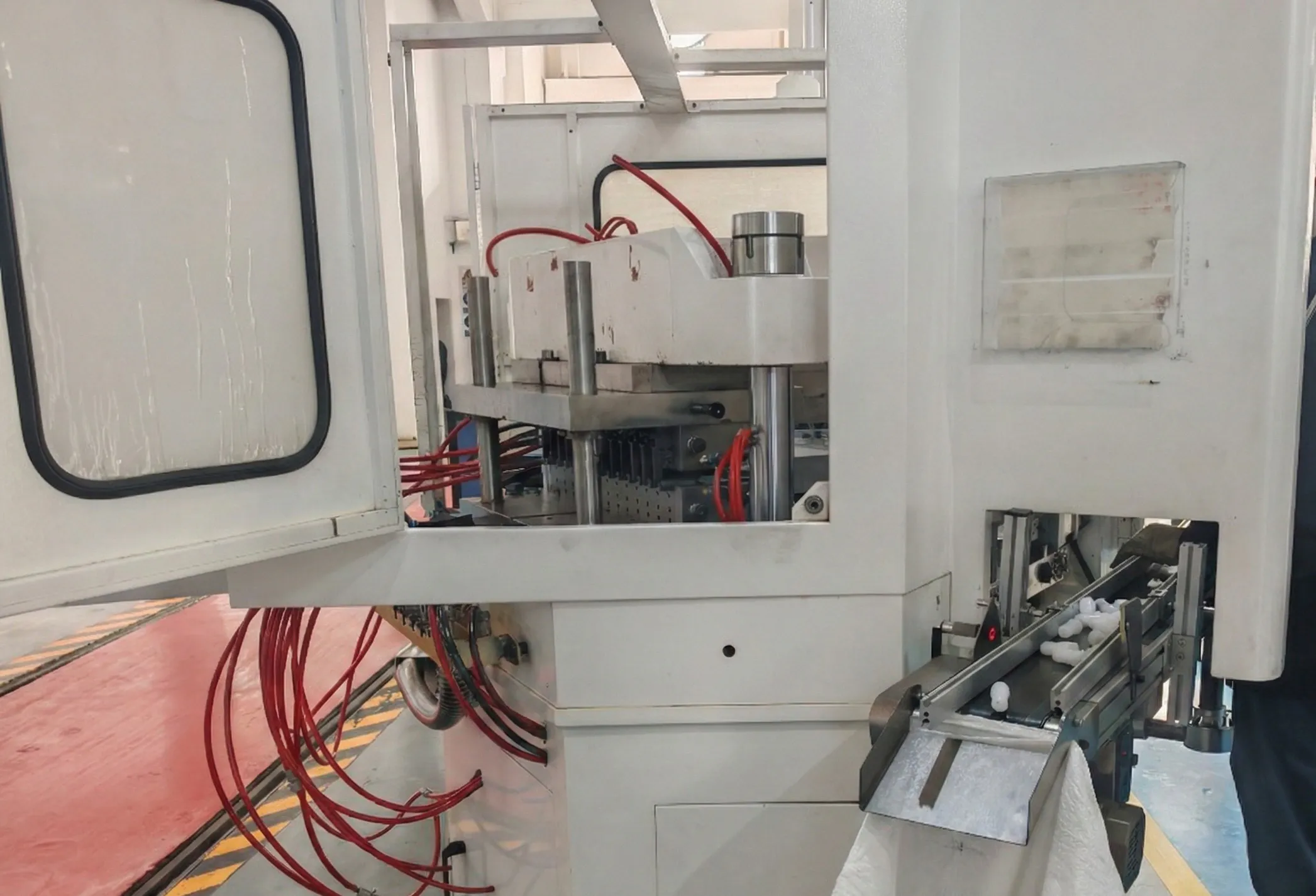
The injection stretch blow molding process integrates three manufacturing steps — injection, temperature conditioning/heat preservation, and stretch blow moulding — into a single continuous cycle within one machine. This integration creates a tightly coupled electrical system where faults in one station immediately affect all others. Understanding the physical layout helps pinpoint which electrical circuit is involved when a symptom appears.
Take the HGY50-V3-EV as a reference example: this fully servo-driven 3-station machine uses 5 servo control systems with a combined motor power of 34.8 kW, runs on 370 V to 400 V supply, and its total installed power is 45.2 kW including 10.4 kW of barrel and screw heating. The machine dimensions are 3,800 mm × 1,200 mm × 2,500 mm. Every electrical subsystem in this machine is interdependent: the turntable servo motor (Yaskawa or WEICHI with TSUNTIEN reducer), the injection clamping servo, the blow mold clamping dual-servo system, the NSK lead screw servo, and the heating control circuit for the screw and barrel must all operate in synchronised coordination. A loss of communication between any two of these systems triggers a halt and generates a fault code in the Inovance PLC alarm buffer.
For larger 4-station machines like the HGY200-V4, the servo motor system (49.2 kW total), injection clamping force of 300 kN, and blowing clamping force of 200 kN per side place greater demands on the power distribution wiring. A voltage imbalance at the incoming supply that might be too small to trip a breaker can still produce enough asymmetry to cause the servo drives to fault during high-torque phases of the injection or blow mold clamping cycle.
On the large-format HGY650-V4 (4-station, 75.7 kW motor power, 400 kN injection clamping, 400 kN blow clamping, machine weight 28 tonnes), the electrical cabling runs are much longer and the number of field devices — proximity switches, temperature sensors, pressure transducers, Parker high-pressure valves, Airtac air cylinders, YUKEN hydraulic control valves — multiplies accordingly. Each of these represents a potential signal fault point, and the troubleshooting sequence must account for all of them.
3. Material System and Heating Circuit Failures
The heating circuit on an انجیکشن اسٹریچ بلو مولڈنگ مشین is one of the highest-priority electrical subsystems from both a production and a safety standpoint. On machines such as the HGY150-V4 and HGY150-V4-EV (10 kW heating power), the screw and barrel are heated by a nano-far-infrared energy-saving heating ring system. On larger machines like the HGY250-V4 and HGY250-V4-B, heating power increases to 15 kW. The materials processed — PET, PETG, PC, PCTG, PP, Tritan, PS, ABS, and PLA — all have specific melt temperature windows. If the heating circuit deviates from the programmed setpoint, product quality is immediately affected: short shots, gate freeze, incomplete preform formation, or degraded material crystallinity.
Heating circuit faults typically present as one of four patterns: a zone showing no heat rise at startup (open circuit thermocouple or failed heating band), a zone reading above setpoint with no response to PLC output (failed solid-state relay or shorted band), a zone oscillating beyond the temperature controller tolerance band (failed thermocouple causing erratic feedback), or the entire heating system showing low power consumption at correct temperature readings (partial band failure leaving remaining bands overloaded).
| Heating Fault Symptom | Most Likely Cause | Diagnostic Step | Corrective Action |
|---|---|---|---|
| Zone reads ambient temperature | Open thermocouple or disconnected band | Measure resistance at band terminals | Replace thermocouple or band |
| Zone over-temperature, no response | Solid-state relay shorted | Check SSR output with multimeter | Replace SSR module |
| Temperature oscillating ±15℃ | Thermocouple signal noise or degraded sensor | Swap thermocouple with known-good unit | Replace thermocouple; check shielding |
| Low amps on all zones | Partial band failure | Clamp-meter each band individually | Locate and replace failed band |
| All zones non-functional | Blown fuse or tripped MCB on heating circuit | Check distribution panel; measure supply voltage | Restore supply; investigate overload root cause |
One specific characteristic of nano-far-infrared heating rings — used on machines from the HGY150-V4-EV onward — is that they operate at higher surface temperature than conventional mica-band heaters. A failure mode sometimes seen in high-humidity environments (relevant for plants near the Colombian Caribbean coast or in highland zones with significant condensation) is moisture ingress into the thermocouple connector, producing intermittent contact resistance that the PLC reads as a rapid temperature spike followed by a drop. This generates a nuisance alarm that clears on restart but returns within minutes. The fix is to seal all thermocouple connectors with self-amalgamating tape and reroute cables away from condensation-prone surfaces.
4. Servo Drive Fault Diagnosis
Servo drive faults are the most commonly reported electrical failures in modern blow moulding production lines. The servo system controls the most mechanically demanding operations of the injection stretch blow moulding cycle — turntable indexing, mold clamping, and blow rod actuation — and is therefore exposed to the highest dynamic electrical stresses in the machine.
Inovance servo drives (the standard on most current machines) generate alphanumeric fault codes that are displayed on the drive front panel and also transmitted to the PLC alarm buffer. The most frequent codes in field service relate to six categories: overcurrent (typically caused by a mechanical jam or a short-circuit in the motor winding), overvoltage on the DC bus (caused by regenerative braking energy with an inadequate braking resistor or a supply voltage spike), undervoltage (supply phase loss, supply voltage drop, or failed contactor), encoder fault (cable damage, connector vibration, or encoder head contamination), overtemperature (inadequate drive cabinet ventilation or blocked heatsink), and communication fault (damaged CANBUS or serial cable between drives and PLC).
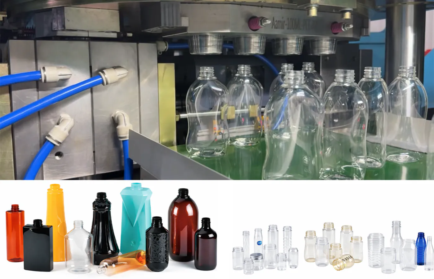
A structured servo fault diagnosis sequence should begin with reading the exact fault code, then checking the supply voltage at the drive input terminals with a calibrated multimeter before the machine is restarted. If the supply voltage is within specification (±10% of rated), the next step is to check the motor insulation resistance with a 500 V megohmmeter between each winding terminal and earth. A reading below 1 MΩ indicates moisture-degraded insulation — a common issue in tropical environments. Readings above 100 MΩ are normal; readings between 1 and 100 MΩ require monitoring but are not yet in the fault zone.
Encoder cable faults deserve special attention on injection stretch blow molding process equipment because the cables run close to the barrel heating elements and alongside hydraulic lines that transmit vibration. The encoder cable shield should connect to earth at one end only (at the drive, not at the motor) to avoid ground loop interference. On machines that have been in service for more than two years without a cable inspection, abrasion damage at cable supports and conduit entry points is a frequent fault source.
5. PLC and Communication System Faults
The PLC control system — Inovance or MiRLE depending on machine configuration — is the central coordinator of the entire blow moulding cycle. PLC faults are less common than servo or heating faults, but when they occur they typically manifest as a complete machine stop with a generic alarm rather than a specific fault code, which makes initial diagnosis more difficult.
The PLC battery is the most frequently neglected component in the control system. Most Inovance and MiRLE PLCs use a lithium coin cell battery to retain programme memory and real-time clock data during power-off periods. When the battery approaches end-of-life (typically 3 to 5 years), the PLC may give a low-battery warning on the HMI. If this warning is ignored and the battery fails completely, a power interruption will cause the PLC to lose its user programme, requiring a full redownload from a laptop with the appropriate programming software. For operators in Colombia who source their machines internationally, having the programme backed up on a USB stick stored in the electrical cabinet is an essential preventive measure.
Communication faults between the PLC and the servo drives (transmitted via CANBUS or EtherCAT depending on machine generation) show as drive-not-responding alarms. The first diagnostic step is to check the communication cable connectors, which can work loose due to machine vibration. The second is to check the terminating resistors at each end of the CANBUS network — these are 120 Ω resistors that must be in place for the network to function correctly. A missing or open-circuit terminating resistor causes intermittent communication errors that are difficult to reproduce on demand and frustrating to diagnose without understanding the network architecture.
The integrated control box temperature management system on current machines keeps the temperature control functions within a single module, which reduces wiring complexity but concentrates the risk. An internal fan failure in this module — which can be caused by dust accumulation in environments where PET dust is present — will cause the module to overheat and generate control errors that mimic PLC faults. Monthly inspection and cleaning of all cabinet ventilation paths is a worthwhile preventive measure in any environment where plastic dust is present.
6. Sensor and Field Device Faults
Proximity switches, pressure transducers, and solenoid valves — the field devices that connect the physical machine actions to the PLC input/output modules — account for a significant proportion of electrical faults on continuous production lines. These devices operate in a mechanically demanding environment: they are exposed to machine vibration, hydraulic oil mist, compressed air exhausts, and the thermal gradients from the barrel heating zones.
Position and limit switches tell the PLC whether the mold is open, closed, in intermediate position, or at the home position. A switch that gives a false signal — either because its mounting has shifted due to machine vibration or because the sensing face has been contaminated with hydraulic oil or PET resin — will cause the PLC to either halt the cycle (if it is a safety-critical switch) or produce an erratic cycle sequence. Checking switch alignment and cleaning sensing faces is a basic but frequently overlooked maintenance task.
The Parker high-pressure valve system used on these machines provides proportional control of blow air pressure (2.0 to 3.5 MPa on most models). The valve coils are electrical solenoids that can develop intermittent faults if the coil insulation degrades due to heat cycling. A solenoid coil resistance that measures correctly on a cold machine but drifts out of specification at operating temperature is a classic intermittent fault. The diagnostic technique is to measure coil resistance both cold and after at least 30 minutes at operating temperature and compare against the rated specification.
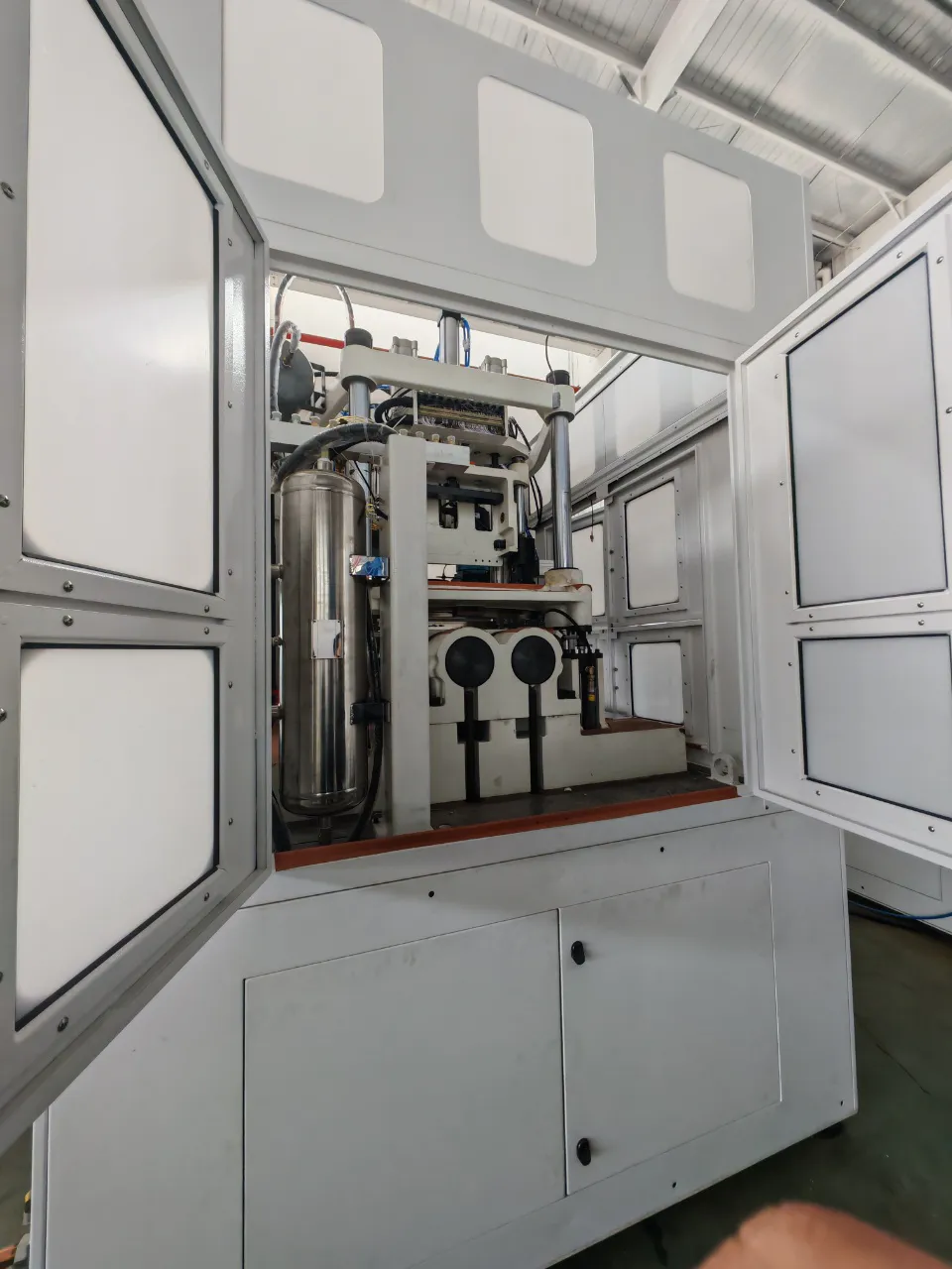
Air cylinder solenoids (Airtac units are standard on current machines) can develop leakage in their exhaust ports that mimics an electrical fault because the cylinder moves slowly or incompletely and the position switch does not confirm arrival within the PLC timeout period. The PLC alarm in this case reads as a position fault rather than a pneumatic fault. Checking cylinder exhaust flow with a hand placed near the silencer is a quick way to distinguish a pneumatic leak from a genuine electrical position fault.
7. Electrical Fault Diagnostic Quick-Reference Table
| Fault Category | Typical PLC Alarm Signal | Primary Cause | First Check | Resolution |
|---|---|---|---|---|
| Servo overcurrent | Drive fault E01 / E03 | Mechanical jam; motor short | Check motor resistance, megohm test | Clear obstruction; replace motor or drive |
| Servo overvoltage | Drive fault E05 | Regen energy, supply spike | Check supply voltage, braking resistor | Add or replace braking resistor |
| Servo encoder fault | Drive fault E08 | Cable damage, connector | Inspect encoder cable for abrasion | Replace cable; verify single-end earth |
| Heating zone no response | Zone over/under temp alarm | Open band or failed SSR | Measure band resistance, SSR continuity | Replace band or SSR |
| PLC communication fault | Drive not responding | CANBUS cable; terminator | Check connectors; measure 120 Ω terminator | Reseat connectors; replace terminator |
| Position switch false signal | Mold position fault | Switch drift; contamination | Clean switch face; check mounting | Realign or replace switch |
| Solenoid valve no actuation | Cylinder position timeout | Coil failure; power supply | Measure coil resistance hot and cold | Replace coil; check solenoid supply fuse |
| PLC battery low | Battery warning on HMI | Battery end-of-life | Check HMI battery status screen | Replace battery; verify programme backup |
| All circuits non-functional | Machine no power | Main isolator, supply fuse | Check incoming supply at main terminals | Restore supply; trace root cause |
| Intermittent random faults | Multiple varying alarms | Ground loop; supply noise | Check earth bonding across machine frame | Improve earthing; add line filter |
8. Electrical Safety and Regulatory Requirements for Colombia and Global Markets
Operating an انجیکشن اسٹریچ بلو مولڈنگ مشین in Colombia places the machine owner and operator within a defined framework of electrical safety regulations that must be maintained as part of any fault response procedure. Working within this framework is not only a legal obligation but a practical protection for maintenance personnel and production staff.
Colombia — RETIE (Reglamento Técnico de Instalaciones Eléctricas): RETIE, enforced by the Ministerio de Minas y Energía, is the primary technical regulation governing all electrical installations in Colombian industrial facilities. It requires that machinery operating above 1,000 V (not applicable to these machines at 370 V to 400 V supply) follow high-voltage protocols, but at low voltage it mandates proper earthing of all metallic enclosures, appropriate circuit protection (MCBs and RCDs), proper labelling of all circuits in Spanish, and lock-out/tag-out procedures during maintenance. Any electrical work on production machinery must be performed by a qualified electrician certified under RETIE requirements. The regulation also requires that switchgear and control panels be accessible for inspection by ICONTEC (Instituto Colombiano de Normas Técnicas y Certificación) certified inspectors.
CE Marking / EU Machinery Directive 2006/42/EC: Machines imported into Colombia from suppliers targeting European or international markets will carry CE marking and documentation prepared under the EU Machinery Directive. The electrical safety requirements of this directive, implemented through EN 60204-1 (Safety of Machinery — Electrical Equipment of Machines), define requirements for supply disconnects, emergency stop circuits, protection against accidental contact, cable sizing, and earthing. These requirements apply to all machines shipped with CE documentation and provide a useful reference framework for Colombian operators even where local regulations do not yet specify equivalent technical details.
NTC 2050 (Código Eléctrico Colombiano): This national technical standard, aligned with the US National Electrical Code, governs wiring methods, cable types, conduit installation, and protection within industrial facilities. It applies to all fixed wiring in the plant — including the supply feed to the blow moulding machine — and specifies requirements for circuit identification, colour coding, and cable support intervals that must be followed when machine supply cabling is installed or modified.
IEC 61508 and Functional Safety: Machines equipped with servo systems and integrated safety functions (emergency stop, guard interlocks, two-hand controls) are expected to conform to IEC 62061 or ISO 13849-1 for the functional safety of their safety-relevant control systems. When diagnosing faults on safety circuits — particularly the emergency stop chain and the guard interlock circuits — it is essential to verify that the safety function is restored and tested after any repair before restarting production.
9. Preventive Electrical Maintenance Schedule
Reactive fault diagnosis is always more costly than preventing the fault in the first place. The following schedule reflects best practice for maintaining the electrical system of a blow moulding machine in continuous two-shift or three-shift production in a tropical industrial environment.
Verify all PLC alarms are cleared and no pending faults are in the alarm buffer. Check HMI temperature readings against setpoints before first cycle. Inspect emergency stop button function by testing at each push-button station. Verify indicator lights are functional on the control panel.
Blow out electrical cabinet with dry compressed air to remove accumulated dust and PET particles. Check servo drive heatsink fans are rotating freely. Inspect all visible cable runs for abrasion or heat damage at contact points. Verify earthing bond connections at machine frame are tight and corrosion-free.
Tighten all terminal block connections in the main panel (vibration causes progressive loosening). Clean all thermocouple connector faces. Test cooling water pressure and flow to the machine oil cooler (target 0.4 to 0.6 MPa). Back up the PLC programme to USB. Check battery status on PLC.
Full insulation resistance test on all motor windings and heater bands. Replace PLC battery if over 3 years old. Perform a full earth continuity test from each machine panel to the main earth bar. Inspect encoder cables over their full run and replace any showing external damage. Review RETIE compliance documentation.
10. Featured Product: One-Step Injection Stretch Blow Moulding Machine
For plants in Colombia and across Latin America looking to upgrade production capacity or replace legacy ASB injection molding machine models, the EP-HGY250-V4 represents a strong option in the mid-to-large format range. This 4-station machine delivers injection clamping force of 300 kN, blow clamping of 200 kN per side, and is designed to be compatible with ASB-70DPH moulds, making it a direct-replacement path for operations running Japanese-standard tooling.
Stations: 4 | Material: PET/PETG
Screw diameter: 55 mm (optional) | Injection capacity: 420 g
Injection clamping: 300 kN | Blow clamping: 200 kN (single side)
Motor power: 67.7 kW | Heating power: 15 kW
Machine size: 6,300 × 2,400 × 3,700 mm | Weight: 16 T
Blow air pressure: 2.0 to 3.5 MPa | Voltage: 370 to 400 V
The electrical system on the EP-HGY250-V4 uses 3 servo pump systems with Inovance or WEICHI servo motors. The turntable drive uses a Yaskawa servo motor with a Taiwan TSUNTIEN reducer. Parker high-pressure valves manage the blow air circuit, and the temperature control system uses an integrated control box for high accuracy and stable operation. The screw heating uses a nano-far-infrared energy-saving heating ring rated at 10 kW, and the entire machine draws a total installed power of 82.7 kW at rated load. For Colombia-based operators who currently use an ASB injection molding machine or AOKI-compatible equipment, this machine offers a cost-effective one-step machine alternative with full local technical support.
11. Compatible Auxiliary Equipment
Reliable electrical performance from an ISBM machine depends not only on the machine itself but on the quality and stability of the auxiliary equipment connected to it. The two most critical auxiliary systems are the compressed air supply and the mould temperature controller.
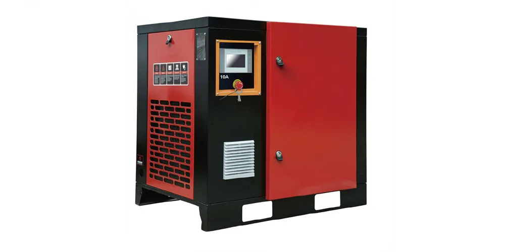
Blow moulding requires clean, dry compressed air at 2.0 to 3.5 MPa. Contaminated air (with oil vapour or moisture) degrades solenoid valve performance, erodes high-pressure valve seats, and introduces humidity that accelerates corrosion on the machine electrical connectors. An oil-free compressor eliminates the oil contamination risk. For PET blow moulding with high-pressure blow air up to 3.5 MPa, specifying an oil-free high-pressure compressor matched to the machine cycle demand is an essential part of the installation design.
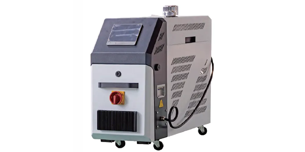
Mould temperature stability directly affects the dimensional consistency of injection stretch blow molding products. A mould temperature controller that delivers unstable water temperature causes the blow mould to expand and contract within a cycle, producing bottles with variable wall thickness and occasional surface defects. Electrically, a faulty temperature controller introduces temperature-related signal noise that can appear on the PLC as a sensor fault if the controller and machine share a common electrical earth. Specifying a matched mould temperature controller with isolated outputs eliminates this cross-interference problem.
12. About Our Production Facility
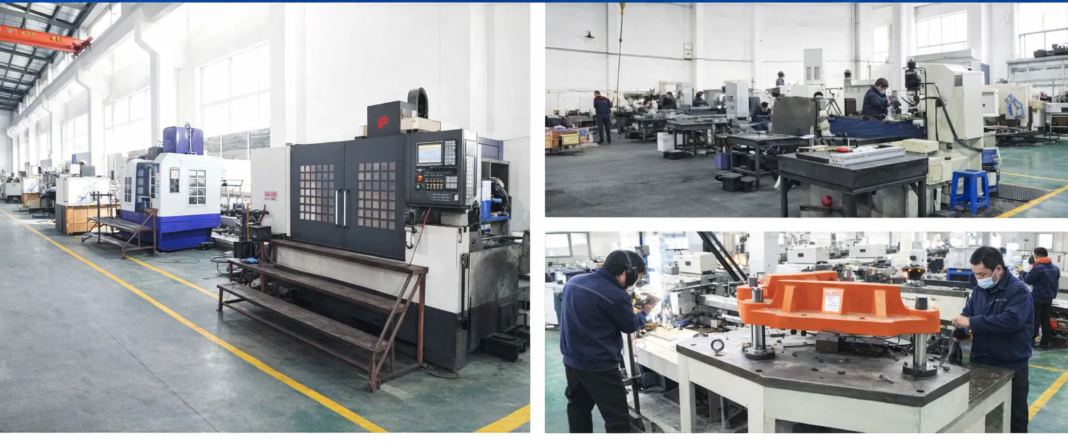
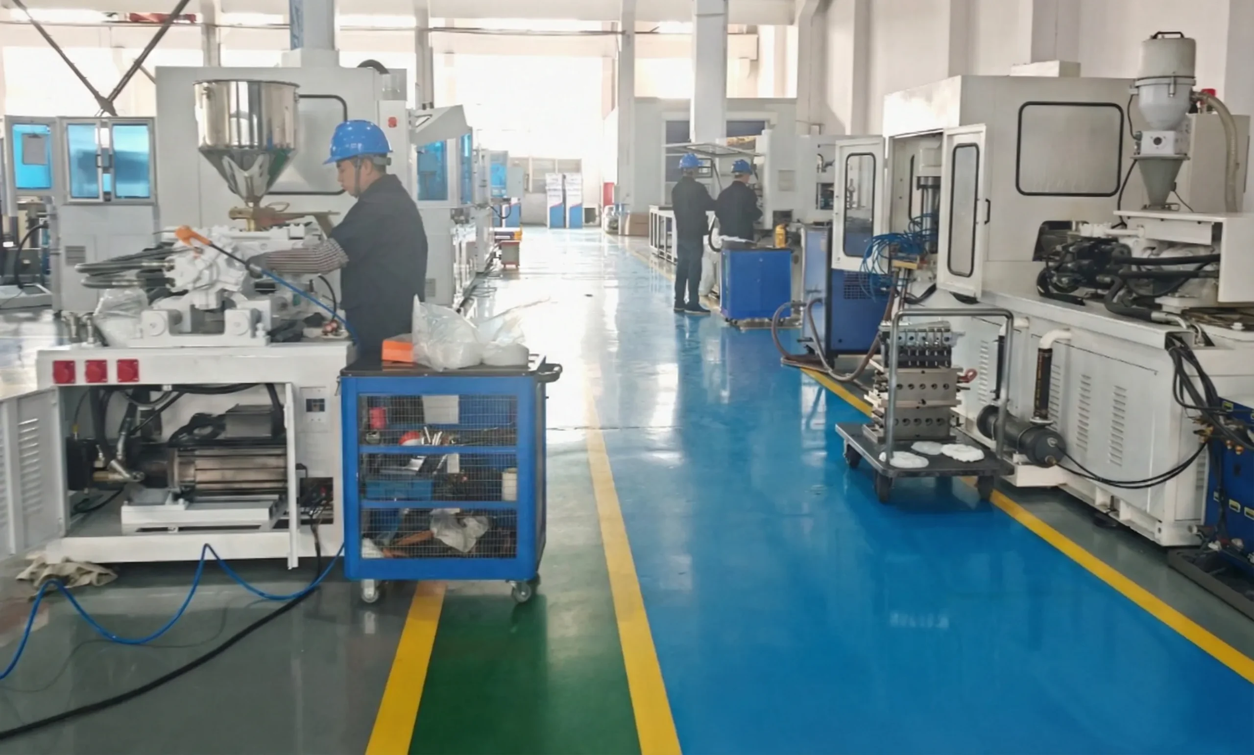
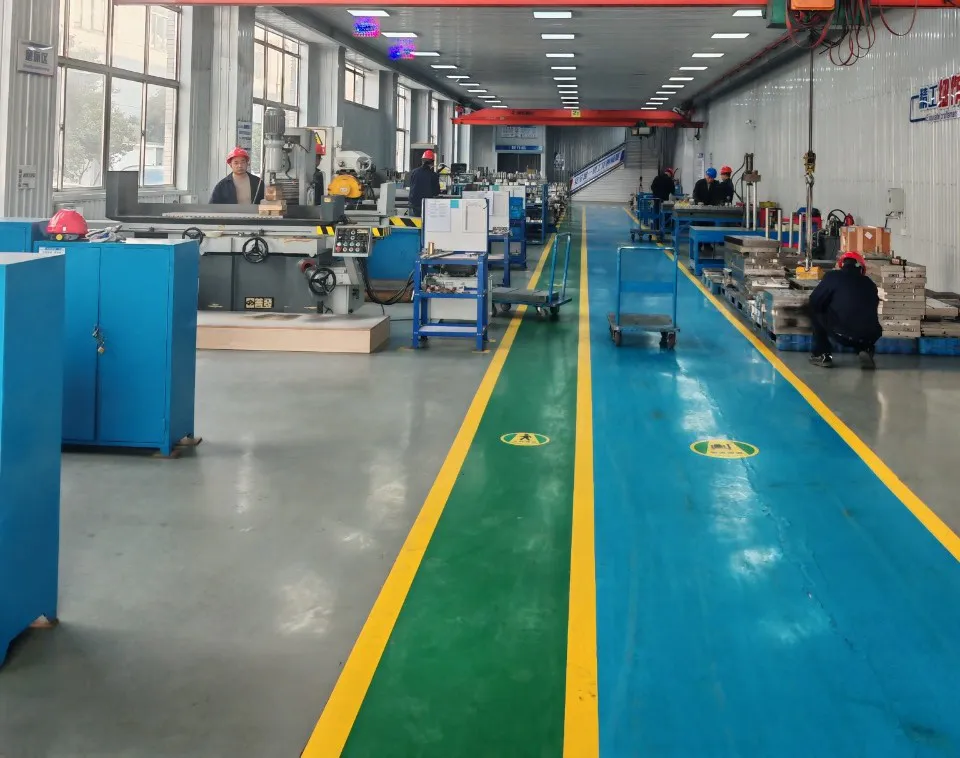
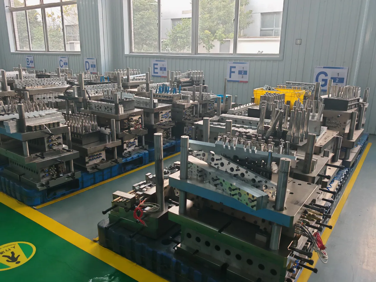
With over 20 years of dedicated focus on the development and manufacture of one-step injection stretch blow moulding machines, our production team has built extensive experience across the full range of machine capacities — from compact 3-station units weighing 3.5 tonnes to heavy-duty 4-station machines weighing up to 28 tonnes and capable of producing containers up to 20 litres. Our production base covers more than 20,000 square metres and operates under an ISO 9001 certified quality management system. All machines are tested at full electrical load before shipment, and the electrical documentation package — including wiring diagrams, PLC programme backup, and servo drive parameter files — is supplied with every machine to support maintenance teams in Colombia and across Latin America. Technical support is available in Spanish for the Colombian and Latin American market.
ورک شاپ
اکثر پوچھے گئے سوالات
Q1. What are the most common electrical faults that stop a blow moulding production line in Colombia?
Q2. How do I read the servo drive fault codes on an Inovance servo system installed in a blow moulding machine?
Q3. What electrical safety regulations must be followed when doing maintenance on a blow moulding machine in a Colombian plastics plant?
Q4. How long does it typically take to get a quote and spare electrical parts for a blow moulding machine in Bogotá or Medellín?
Q5. What is the best way to prevent blow moulding machine electrical faults in a humid tropical environment like coastal Colombia?
Q6. How do I know whether my blow moulding machine needs a new machine supplier or just electrical repair?
Q7. Which injection stretch blow molding machines are most suitable for beverage and water bottle production in Colombia for 500 ml and 1.5 litre containers?
Q8. What are the main electrical differences between a fully servo-driven blow moulding machine and a hydraulic servo pump machine in terms of electrical fault patterns?
Q9. Where can I find injection stretch blow molding machine manufacturers that offer Spanish-language technical support for the Colombian packaging industry?
Q10. How does the electrical system of a one-step injection stretch blow molding machine compare to that of a two-step system and what are the maintenance cost implications?
ایڈیٹر: PXY